Introduction
Depending on the different values of inductors and capacitors used in the ladder filter, different kinds of responses can be had for the same cut-off frequency. The kind of behavior you can expect from a filter depends not only on its order, but also its family.
Filter Families
For a given cut-off frequency and filter order, there are multiple solutions for component values. Depending on these values, different responses can be created. Two filters with the same component arrangement, the same cut-off frequency, and the same order, can have different component values and different Bode plots. The most common filter families are the Butterworth, Chebyshev, Cauer, and Bessel filters. They each have advantages and disadvantages. Which one is best will ultimately depend on your application. In this post we will go over these 4 families of filters, and study their response curve for an identical order and cut-off frequency. In the following paragraphs, all filters will be third-order low-pass filters with a 10kHz cut-off frequency.
The Butterworth Family
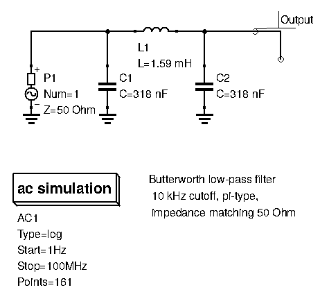
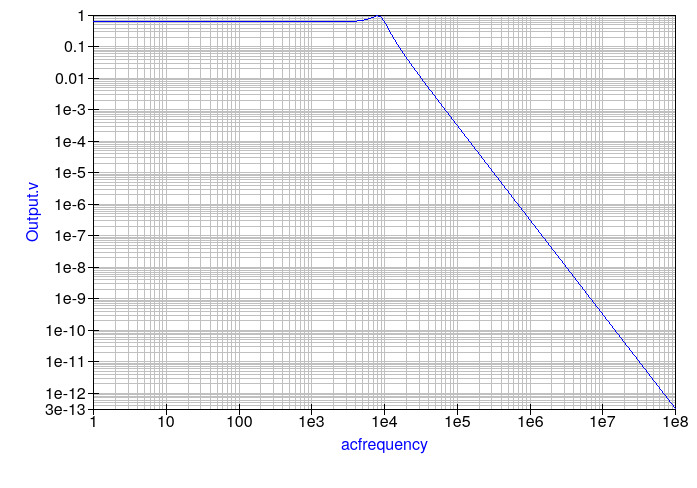
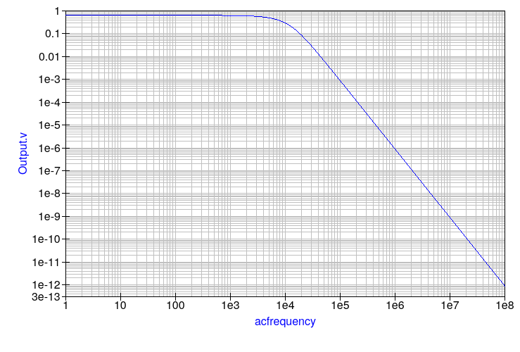
Let’s observe the response curve. Keep in mind the y-axis still represents voltage, not power. We still have the predicted 30dB of voltage drop per decade of frequency shift, as expected of third-order filters. Look at the pass-band, the range of frequencies before the cut-off frequency: the curve is extremely flat with no variations. There is just a slight bump when approaching cut-off frequency, where resonance occurs.
Attenuation also increases gradually after the cut-off, and much higher frequencies are essentially non-existant after the filter.
A Butterworth filter is used when you want a flat passband (no non-linearities in the output), and don’t mind having a relatively smooth roll-off.
The Chebyshev Family
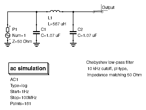
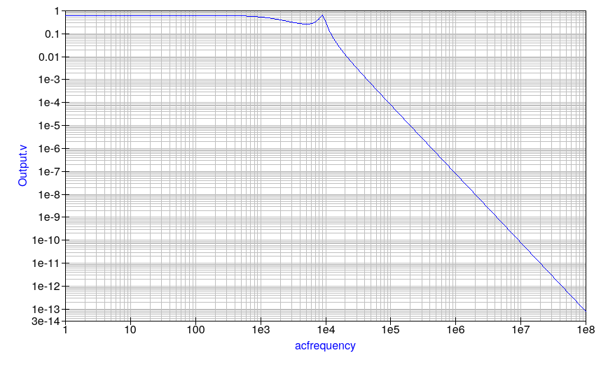
The thing that stands out the most here is that when approaching the cut-off frequency, we observe some ripple in the pass-band: the passband is no longer flat as it was with the Butterworth family. At the cost of some ripple, however, we have a steeper roll-off curve at the cut-off frequency. Both ripple and the steeper initial curve at cut-off become more apparent the higher the filter order is. Pass-band ripple is a design parameter for Chebyshev filters. We can design for low or high ripple. However, lower ripple (better pass-band linearity) comes at the cost of smoother roll-off after cut-off. That said, even small amounts of ripple can still give the filter a good, steep response curve after cut-off.
While the initial roll-off is steeper, far into the stop-band (the range of frequencies we want to block: here, everything after the cut-off frequency), we still have the 30dB of voltage drop per decade of frequency shift, as expected of our third-order filter.
A Chebyshev filter is used when you need a steep roll-off, and can tolerate some non-linearity in your output.
The Cauer Family
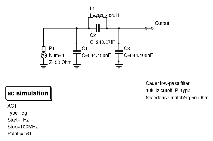
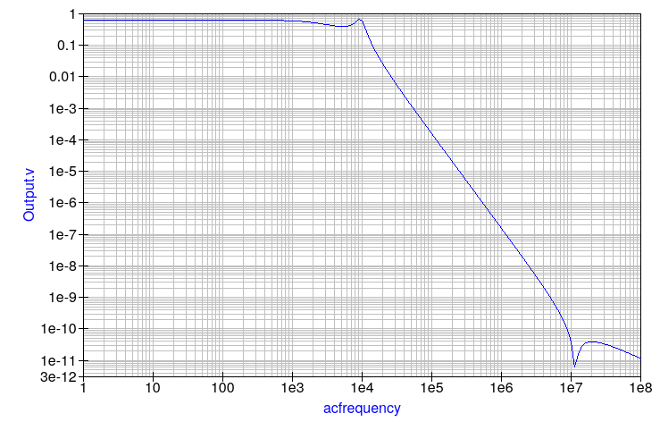
Just like the Chebyshev family of filters, this Cauer filter has some ripple in the passband, thus deteriorating output linearity. The roll-off after the cut-off frequency is even steeper than for the Chebyshev family, greatly attenuating frequencies that are close to the cut-off. However, take a look further up in the stop-band. The curve doesn’t just decrease continuously: there is a notch at around 10MHz, and the roll-off after that is very shallow. This is the downside to the Cauer family: attenuation in the far stopband is limited.
When designing Cauer filters, many parameters can be set: ripple amount, and the position of the first notch, thereby guaranteeing a steep roll-off from the cut-off frequency up until the frequency of the first notch. We can also set the minimum attenuation we want in the far stopband.
The Cauer filter is useful when you need a very steep roll-off, and don’t mind sacrificing some far stop-band attenuation or output linearity.
The Bessel Family

At first glance this filter’s response doesn’t look that much different from the Butterworth filter we studied earlier. It shares the same characteristics: a flat passband response (thus ensuring great output linearity), a relatively smooth roll-off, and complete attenuation far into the stop-band.
Bessel filters however do offer an extra advantage that is not shown on the Bode plot: it has a near constant group delay in the passband, and smooth group delay changes near the cut-off frequency. What is group delay and why should we worry about it? Different frequencies take a different amount of time to go through the filter. In extreme cases, such as near the cut-off frequency for all previous 3 filter families, frequencies close together won’t arrive at the output at the same time. This delay will greatly degrade our signal, sometimes to the point of rendering it incomprehensible.
For uses when a smooth group delay is needed both in the pass-band and near the cut-off, a Bessel filter is used.
Filter Architecture: Tee and Pi
For a given order of LC ladder filter, there are two ways to arrange components to create the same filter: the “Tee” architecture, and the “Pi” architecture. They focus on which component the entry signal will see first: the inductance, or the capacitor.
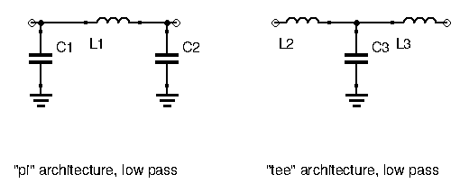
Once you look at the two architectures, it’s easy to understand why they are named that way. Are there any advantages to choosing one over the other? In terms of circuit performance, no there isn’t. In terms of building ease, PCB real estate, and cost-effectiveness, however, there is. When designing odd-order filters, there will always be one kind of component, either the inductors or the capacitors, that are in the minority. There will always be either one fewer capacitor than inductors, or one fewer inductor than capacitors. Since inductors are either costly to buy, or time consuming to build, it’s always advantageous to choose the architecture that allows for the fewest possible amount of inductors. Hence why all the above filters were made using the “Pi” architecture, requiring 2 capacitors and 1 inductor (apart from the special case of the Cauer filter which requires 2 of each).
Conclusion
In this post we’ve presented the most commonly used filter families and their advantages, disadvantages, and use cases. Let’s review them:
- Butterworth: Flat passband, smooth roll-off, great attenuation far into the stopband
- Chebyshev: Ripple in the passband, steep roll-off, great attenuation far into the stopband
- Cauer: Ripple in the passband, very steep roll-off, limited attenuation in the stopband, more complexity in building
- Bessel: Flat passband, smooth roll-off, great attenuation far into the stopband, constant group delay in the passband, smooth group delay variations near the cut-off frequency
Notice here we still only talked about low-pass filters. This is because when it comes to filter design, the low-pass filter is the basis for all calculations. If you know how to design a low-pass filter, you can then easily design all the other kinds of filters. In the next post we’ll go over actual filter design.