When it comes to oscillators, one technology that has greatly risen in popularity these past few years is DDS – Direct Digital Synthesis. An increasing number of ham projects are using DDS chips, and it is possible to find RF-capable chips at relatively affordably prices. With easy-to-use micro-controller development boards such as the Arduino, using these digital components has become more accessible. Outside the ham world, DDS is also omnipresent, and nearly all commercial RF equipment will feature this technology. And for good reason, DDS presents many great advantages and solve many problems that plagued analog-only oscillators.
What is DDS?
DDS, or Direct Digital Synthesis, is a form of frequency synthesis. Similarly to PLLs, DDS revolves around creating a broad range of frequencies out of a single fixed frequency oscillator (most often, a stable quartz oscillator). Unlike PLL however, DDS does not use feedback: it is an open-loop circuit, hence the name “direct”. While PLL blends both analog and digital circuitry, DDS chips are essentially digital only components.
So, how does DDS work? Let’s take a look at its architecture first, and explain the role of each block:
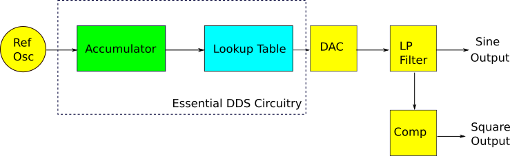
Reference Oscillator
Just like PLLs, DDS chips need a stable reference frequency to work with. The stability and accuracy of this oscillator influences the stability and accuracy of the DDS output. Most often, a stable quartz oscillator is used.
Tuning Word
The accumulator has two inputs, one of them being the tuning word. A DDS is programmed to output a certain frequency based on this tuning word. It is a specific sequence of bits that tells the accumulator to overflow after a certain number of reference oscillator pulses have been received.
Accumulator and Lookup Table
Depending on the tuning word it has received, the accumulator will overflow after a certain amount of reference oscillator pulses has been received. When the accumulator overflows, it looks at the next entry in the lookup table. The accumulator acts like a counter.
The lookup table is a hard-coded series of coordinates that define a sine-wave. Cycling through it will produce a sine output. Cycling through it at a faster rate will produce a higher frequency sine wave, while cycling through it at a lower rate will produce a lower frequency sine wave. How do we vary the cycling speed of the lookup table? We ask the accumulator to skip over certain points. The more point we skip, the faster we will cycle through the table. The lowest frequency possible is attained when we cycle through the table without skipping any points.
To carry out this task, the accumulator accepts a tuning word. The higher the tuning word (in binary), the more points it will skip in the lookup table, and the faster the output signal will be. The lower the tuning word, the less points in the lookup table are skipped, and the slower the output signal will be.
Now, this was the simplest possible way I can explain the inner workings of both the accumulator and lookup table. While not completely accurate, it should give you a good enough intuitive understanding of how DDS actually work. In the datasheets, the accumulator is called a phase accumulator, and for good reason: the lookup table it retrieves information from is actually called a phase-voltage lookup table, translating phase into a specific amplitude.
Together, the accumulator and the lookup table are what constitutes the core of DDS. The rest of the components on the chip are just gravy.
DAC – Digital to Analog Converter
The output of our lookup table may contain raw coordinates for a sine wave, but its output is digital only, consisting of a sequence of bits. This cannot be exploited as is, and needs to be converted to the analog realm before becoming of any use. This is where the DAC -Digital to Analog Converter – comes in. It takes a sequence of bits, and outputs the corresponding amplitude.
Low-pass Filter
You’ll notice that the output of the DAC is a series of discrete voltages. It takes on one value, then another, and another. This results in a staircase waveform. This raw output is littered with harmonics and spurs, and cannot be used as is in any serious RF applications. Luckily for us, most DDS chips understand this and insert a low pass filter after the DAC, smoothing out the waveform and making it look closer to a true sine wave. The filtered sine wave is then available for use by the user. It is also sent to the comparator.
Comparator
The lookup table was coded to only give a sine output. Since digital (and also some analog) circuits often need square waveforms, something needs to be done to able to use DDS as a digital clock generator. Transforming a sine wave to a square wave is very easy: a simple comparator does the job well. When the input of the comparator is positive (the positive half cycle of a sine wave), the output is HIGH. When the input of the comparator is negative (the negative half cycle of a sine wave), the output is LOW. The output of the comparator is thus a digital clock signal.
DDS Frequency
There is a relationship between the tuning word, the reference oscillator frequency, and the DDS output frequency, and it is as follows:
![\[ f_{out} = \frac{T}{2^n} \times f_{ref} \]](http://modernhamguy.com/wp-content/ql-cache/quicklatex.com-44220a577d5813da427991c48951127e_l3.png "Rendered by QuickLaTeX.com")
Where:
 is the tuning word, with values able to range from 0 to
 is size of the accumulator: the maximum amount of pulses it can store before overflowing
 is the reference oscillator frequency
You will find this equation in every DDS datasheet. This is the fundamental DDS equation. We notice that to change the output frequency, we can either modify the reference oscillator frequency, or change the tuning word. Both methods have their use, but changing the tuning word is the most straightforward, and easiest, way. A DDS is connected to a micro-controller which then gives the DDS the tuning word, fixing the output frequency. The micro-controller can be hooked to up to any number of user-interaction elements, such as rotary encoders or push-buttons. It can then be easily programmed to modify the tuning word depending on the user’s interaction with these elements, thereby modifying the output frequency.
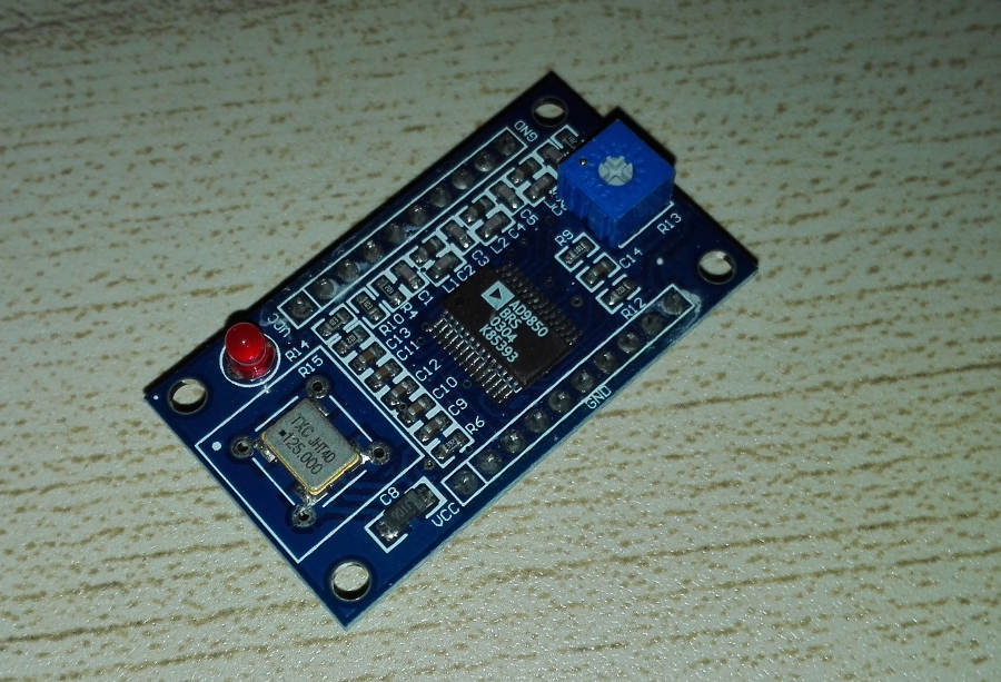
A common DDS project is hooking up an Arduino to a popular DDS chip, such as the AD9850 from Analog Devices, and using a rotary encoder to switch frequencies. A small LCD display is then added to show the output frequency in real time.
DDS Advantages
Being a purely digital technology gives DDS chips great advantages. Coupled with the fact that they don’t need a feedback loop like the PLL does and the result is extremely fast frequency switching speeds: a DDS is very agile.
While it is possible to get relatively good frequency resolution with Fractional-N PLLs, DDS have a much better resolution, with frequency steps in the mico-Hertz being common. Best of all, that resolution doesn’t impact frequency switching speeds as it does for PLLs.
Finally, DDS chips can output a very wide range of frequencies. The popular AD9850 for instance can cover the entire HF band on its own.
DDS Disadvantages
DDS does have some downsides however. First of all, even if they have become more affordable these past few years, DDS chips are still relatively expensive. On the less pricey side, expect to spend around $20 per chip. And don’t forget, a DDS chip needs a whole digital infrastructure to actually do something: you’ll need at least a micro-controller and some sort of user-input device.
Another downside, at least for experiments like us, is that these chips are nearly always only available in SMC – Surface Mount Component – packaging, making them much more difficult to solder and especially test drive them. Various solutions exist however: you can find breakout boards featuring a specific DDS chip. These are great to test the chip before committing to a design. Be wary of some sellers on eBay however. The price may be attractive, but counterfeit chips do exist. Another solution, and one that I prefer, is to buy the DDS chip from a reputable supplier (Mouser, Digikey, or your regional equivalent) and get a SMC-to-DIP converter. These are cheap and readily available in hobbyist electronic retailers (Sparkfun has plenty in stock). This DOES require you to to some SMC soldering, but the end result will give you a breakout board you can use for testing and refining your designs, with a chip you are certain is genuine.
Being purely digital also brings some downsides, the most obvious one being power consumption. However, a lot of improvements have been made in this regard, making power consumption almost a non-issue when considering DDS chips in your design.
All the above are problems that are either not too serious or can be worked around. However, DDS has one major downside: its spectral purity is really not great. The manufacturers will go to great length to convince you otherwise, saying their chip produces “spectrally pure” sine waves. But the truth of the matter is that DDS chips suffer greatly from spurs in their output signals, more so than fractional-N PLLs. Some things can be done to mitigate this effect, the most common of which is simply to add a low-pass filter as an extra stage after the DDS. However, doing so presents a new problem. After we design a low-pass filter, we can’t change its cut-off frequency. If we choose a lower cut-off frequency, we get rid of more spurs and parasitic harmonics, but we sacrifice some of the DDS’ frequency range (specifically, frequencies near or after the cut-off frequency won’t be usable). If we choose a higher cut-off frequency, we can keep more of the DDS’ frequency range, but we only marginally improve spectral purity. For RF work, the spectral purity of DDS is good enough to be used for many applications. However, you should be careful when using it as a front-end mixer: even after extensive filtering, the spurs will degrade receiver performance.
Conclusion
Hopefully this article has shed some light on DDS technology. More in-depth explanations on DDS technology is usually available in the datasheet of the DDS chip you want to use. Otherwise, there are great articles from Analog Devices on the subject if you wish to go deeper.
DDS chips aren’t a particularly recent technology, but they have only become cheap and reliable enough relatively recently. As is the case for all the shiny new tech, DDS chips are nearly always only available in SMC format. This is a trend that will not change, and if we want to make the most of today and tomorrow’s technology, learning to use and solder SMC packages will become increasingly necessary.
If you want to try out a DDS chip for your own projects, I suggest looking at Analog Device’s lineup of DDS chips. I’ve mentioned the AD9850 before, but there are other options, both cheaper and more expensive.