Introduction
Filters are an important building block you will find in nearly all fields of electronics. They are of particular interest to the ham radio experimenter and RF designer. Out of all the building blocks of radio electronics, filters are perhaps the most simple to understand. Simple doesn’t mean unimportant however, as filters are a necessary component in every radio circuit you will design and build. In this section, we’ll learn the about the different types of filters, the vocabulary needed to understand filter performance, and we’ll also delve a little bit into the math that determines filter behavior.
Why we Need Filters
What do filters actually do? Simply put, they allow or block certain frequencies. That’s it. Now depending on how that filter is built (we’ll get into that shortly), the frequencies it will let through will vary.
How can this be useful? Filtering can be necessary before transmitting a modulated signal to the antenna to avoid out-of-band transmission and achieve a cleaner signal. Filters are usually necessary at the input of a receiver, only allowing frequencies close to the ones you want to receive through. Your speech signal coming from a microphone might also need to be filtered, just like the audio signal from your receiver. There are many, many more examples, but I think you see the point. Filtering is an important cornerstone of RF design. Anytime we want to process analog signals, filtering will be needed.
Filters are also the first obstacle new experiments and homebrewers come across. It’s possible to find most of the other “blocks” needed for a receiver as ICs (oscillators, mixers, amplifiers). Just following the datasheet’s application notes and recommendations, you can build a simple working circuit. However, one thing you usually won’t find for sale is a dedicated filter for your circuit. Fortunately, filters are probably the simplest building block to understand and design. There are tons of resources out there for novice builders that require nearly zero theory or math, and allow you to craft a working filter.
Filter software is great, and we will get around to using one. However, I find it always best to understand the theory behind what you’re building. So before we start designing a working filter, let’s start with some basic theory and vocabulary. Not only will you understand what the software will eventually be doing for you, but you will also know what kind of filter is best for your application (and there are plenty to choose from!).
Filter Components
So, what are filters made of? The most common filters you’ll come across are passive filters, and these only use capacitors, inductances, and sometimes resistors. To understand why these components are used, let’s recall the impedance of both capacitors and inductances:
- for a capacitor:

- for an inductance:

With  . This means that capacitors let higher frequencies pass through, while inductances let lower frequencies pass through. Said otherwise, capacitors block low frequencies (
 is higher when
  is lower), while inductances block higher frequencies (
 is higher when is higher).
Now, at what point frequencies are considered to be “high” or “low” will depend on the value of capacitance of inductance chosen.
The Low Pass Filter
To see these components in action, let’s study a simple application: a low pass filter:
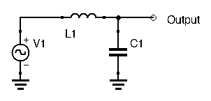
How does this filter work? We’ve seen that inductances let low frequencies pass, but block higher frequencies, while capacitors let high frequencies pass, while blocking lower frequencies. Here, the higher frequencies are blocked (not entirely, they are attenuated) by the inductor, and what little remains can pass through the capacitor to ground. Hence, higher frequencies do not show up at the output. The lower frequencies can pass unhindered through the inductor and to our output. Since the capacitor prevents these lower frequencies from going to ground, we can expect most of the lower frequencies’ power to show up at the output.
We can find the transfer function of this filter. Using the voltage divider formula with the complex impedances, we obtain:
![\[ H(j\omega) = \frac{V_{out}}{V_{in}} = \frac{\frac{1}{jC\omega}}{\frac{1}{jC\omega} + jL\omega} = \frac{1}{1 - LC\omega^2} \]](http://modernhamguy.com/wp-content/ql-cache/quicklatex.com-e0a962474b464192bb099f80253119ef_l3.png "Rendered by QuickLaTeX.com")
By introducing  , we obtain:
![\[ H(j\omega) = \frac{V_{out}}{V_{in}} = \frac{1}{1 - \frac{\omega}{\omega_0}^2} \]](http://modernhamguy.com/wp-content/ql-cache/quicklatex.com-4c8111e456d124ecaba01a4f705e0a9c_l3.png "Rendered by QuickLaTeX.com")
Looking at this transfer function, we can make the following statements:
- when
 tends to
  ,
,  tends to zero. High frequencies are blocked.
 - when
 ,
,  . Low frequencies pass through unhindered, with no gain.
You’ll notice something interesting happens when  :
:  seems to go infinite. This is the circuit’s resonant pulsation. In reality, the output cannot go infinite because there are always resistances in the circuit, even if it’s just the wiring. While the capacitor won’t exhibit much parasitic resistance, inductors are notorious for introducing resistance in circuits. Because of these resistances, the output at resonance will be dampened. Still, at resonance the output of our filter can still have high voltage (greater than 1), depending on how much resistance has been introduced, mostly by our inductor.
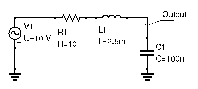
Let’s draw the Bode plot for this circuit, with a series resistance for our inductor of  , and a resonant frequency
  (which means an
  equal to
  ) , just as an example.
 We can clearly see the resonance in effect at 10kHz. The cutoff frequency, the frequency at which voltage gain drops by a factor of
  , is around 15kHz. The resonant frequency and cutoff frequency are usually close together.
Another important thing to point out is by how much the output is attenuated after the cutoff frequency. If you look closely, for every decade of frequency shift (from 100kHz to 1MHz, from 1MHz, to 10MHz,…), the gain drops by a factor of 100, or 20dB. Note that the curve represents voltage, and not power. If converting to power, then the gain drops by a factor or 10000, or 40dB for each decade of frequency shift (power is proportional to the square of the voltage). This is no coincidence: we will explain this shortly.
Finally, we also want to look at the shape of the response curve in our passband: the frequencies we want our filter to let through. Here, it’s everything from 1Hz to 10kHz. We can see the response is mostly flat. The flatter the response curve in our passband, the better the filter will be: we want as little variation in gain as possible in our passband.
Filter design relies on the low pass filter. From it, any other kind of filter may be designed. The different methods and calculators all use the low-pass filter as their base. If you understand the low pass filter, you can design any kind of filter you want.
Filter Order and Roll-off
Every filter you design will have a certain order. Finding the order of a filter is actually very simple: simply count the number of capacitors and inductors in your filter. That is your order. The filter introduced in the previous paragraph has 1 capacitor and 1 inductor, thus it is a second-order filter.
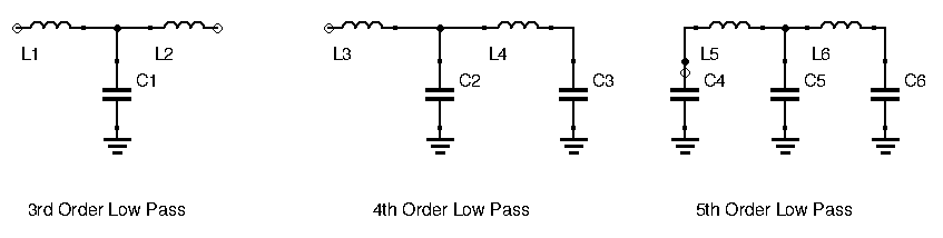
Filters created by chaining inductors and capacitors are called ladder filters. Here are examples of third, fourth, and fifth-order filters:
The order of a filter has direct consequence on its performance, and most importantly its roll-off. Roll-off is the amount by which the input is attenuated after the cutoff frequency for every decade of frequency shift. In our previous example, roll-off was 20dB/decade voltage wise, or 40dB/decade power wise. A general rule is that roll-off is N 20 dB/decade power wise, or N10 dB/decade voltage wise, N being the order of the filter.
A greater roll-off means a steeper response curve, and thus unwanted frequencies are quickly attenuated. Less roll-off means a more gentle response curve, and even after the cut-off frequency there will still be a non-negligible amount left of the original signal at the unwanted frequencies.
Higher order filters are therefore offer more performance at the cost of added circuit complexity, components, and PCB real estate.
Active and Passive Filters
We did a good job grasping the basics of filtering with passive filters. But there is another kind of filter that can be designed: the active filter. Contrary to their passive counterpart (not including resonance), the active filter can have a gain greater than 1. To achieve this, they incorporate an active device: nearly always an Op-Amp.
A gain higher than unity is not the only advantage they offer. To create high performance higher-order passive filters, we need to use inductors. However, inductors take up a lot of PCB real estate, and most often (for the average ham or electronics enthusiast at least) they need to be made by hand. Inductors also have relatively low quality factors (they have a non-negligible parasitic series resistance). This makes actually building passive circuits with inductors time-consuming. Active filters can achieve high performance without using inductors. Higher order active filters can be made by simply adding capacitors.
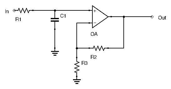
Here is an example of a first order active filter:
The active filter also has its downsides. For starters, since it uses an active device, it requires a power supply, most often a split power supply with both negative and positive voltages. Secondly, its range of frequency operation is restricted by the active device’s bandwidth. For higher frequencies, active filters won’t get the job done. We’ll have a post specifically dedicated to active filters.
Conclusion
If you came in knowing nothing about filters, or just wanted a refresher, I hope this introduction was helpful to you. There are definitely a few more things to go over before we can confidently design our own filters, but already you have the basics. In the next post we’ll go through the different kinds of passive filters and their characteristics.