Introduction
Up until now we have only studied and used discrete components for amplifiers. Up until the advent of Integrated Circuits, or ICs, building your amplifier out of individual discrete thru-hole components, such as transistors, resistors, and capacitors, was the only way. While amazing things were (and still are today!) created with discrete technology, discrete active devices had imperfections and limitations that had to be worked around. Bipolar Junction Transistors have a  that can vary a lot, and its
  depends on temperature. When using JFETs, we have to design circuits knowing that the cutoff frequency can vary by a factor of 3. All discrete active devices have limited gain, and if want to use feedback, that gain is drastically reduced. Furthermore , unless we create huge gain by cascading amplifiers together, the loop gain may not be high enough to completely rid ourselves of transistor variability.
As said before, if you’re dead set on only using discrete components, all these problems can be worked around, at the cost of some circuit complexity and PCB real estate. If you don’t want to use ICs, you can still build formidable circuits, including receivers and transmitters.
However, the advantages that ICs present, and the fact that they have changed the electronic landscape when they were introduced, would make it a shame not to understand them and leverage them in our own designs.
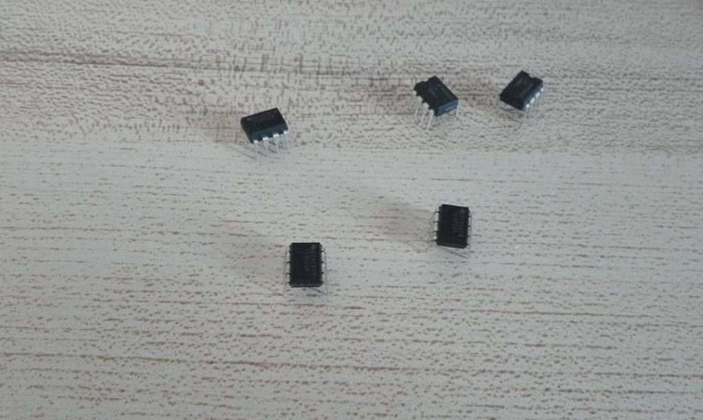
Probably the most common IC you will come across is the Operational Amplifier, or Op-Amp for short, and for good reason. It is a fundamental building block in nearly all fields of electronics.
What are Op-Amps
Imagine a perfect amplifier. Ideally we’d want huge gain, infinite input resistance so as not to load the previous stage, and zero output resistance so that we could drive any load. When only using transistors, this ideal amplifier seems pretty much out of reach. It turns out however, that there is an active device that very closely resembles this perfect amplifier: the aforementioned Operational Amplifier.
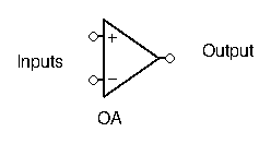
Op-Amps has two different inputs: an inverting input, and a non-inverting input. They have just one output.
The output voltage depends on the difference of the signals applied at the two inputs. If there is more voltage present at the non-inverting input than at the inverting input, then the output will go positive, and vice versa.
Notice here I didn’t give any values or equations linking the output to the input. This is intentional. Op-amps have such huge gain that even the most minuscule difference in voltage will cause the output to saturate. Thus, when using an op-amp as is (open-loop):
- if more voltage is present at the inverting input:

- if more voltage is present at the non-inverting input:

The saturation voltage depends on the op-amps power supplies:
Most Op-Amps require a split power supply: a positive (V+) and negative voltage (V-). These supply voltages are usually omitted on the schematic. The saturation voltage is very close to these supply voltages.
Some Op-Amps only require a single positive power supply, the other pin being grounded. Whatever the case, the output voltage is always constrained by the power supply. An Op-Amp cannot give more voltage that it is supplied with.
Let’s take a look at the TL081 Op-Amp’s datasheet:
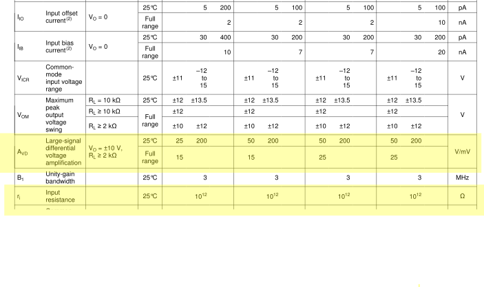
I’ve highlighted the gain and input resistance. The gain is expressed in V/mV, so to get the real gain, we multiply the given figure by 1000. Both gain and input resistances are huge, beyond anything we’ve seen in any circuit beforehand. For all intents and purposes, they can be viewed as infinite. Likewise the input currents are negligible, in the pA range.
The only negative thing we can find on this datasheet is the very poor bandwidth: there is no more gain at 3MHz. We’ll talk more about this in the next paragraph.
Negative Feedback
Now, if we can only get two values out of our Op-Amp ( and
and  ), then how can we make an amplifier out of it? It turns out an ideal amp with infinite gain is actually useless at amplifying signals in the real world, if used as is.
However, the Op-Amp was not meant to be used in an open-loop configuration. Instead, the Op-Amp thrives on negative feedback. It’s near infinite gain  makes it so any loop gain
  will also have a huge value. This means that, when using negative feedback with an Op-Amp, the closed-loop gain of our circuit will be completely independent of our active device (the Op-Amp itself), and instead depend completely on our feedback network
  . This makes designing amplifier circuits with Op-Amps very simple.
Common Use Cases
There is a reason why Operational Amplifiers are named that way: they are great at math. Creating circuits that add, subtract, or emulate other mathematical function is relatively easy and only requires a few components.
In the world of ham radio, you will very often find an op-amp (or more) as an audio amplifier in the last stage of your receiver. If you’ve ever tried to build a receiver from the ham literature, chances are pretty good it’s audio stage had an op-amp (chances are it was also the LM386, a very popular op-amp for ham radio design).
Another common use for Op-Amps for building active filters. Passive filters are made of passive components: resistors, inductances, and capacitors. These filters always have a gain less than unity, which makes sense since no extra power is added, and a bit of power is lost due to the resistive elements in the filter. Active filters, on the other hand, use op-amps in addition to passive components, and are able to have a gain greater than unity. A whole section dedicated to filters will be available, so don’t worry if you don’t know how they work very well yet.
It used to be that Op-Amps had pretty bad bandwidth, even with feedback, and that restricted their use to non-RF applications. Nowadays however, you can find specific high performance Op-Amps tailored to RF applications. It is still pretty rare to find an Op-Amp as the amplifier for the RF stage in ham circuits though.
There are a TON of other uses for Op-Amps, but with just these you already have the bulk of use cases for RF design.
The Only Thing you Need to Know
Now that we’ve established what an Op-Amp is and what it is used for, how do we exploit it in practice? In an open-loop configuration, as seen above it’s pretty easy. But if we want to make an amplifier, we need to add in negative feedback. To achieve this, a portion of the output must be redirected to the inverting input. Here is an example:
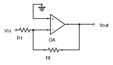
What happens then? In the above example, let’s assume  increases from 0V and becomes positive. Since it is applied at the inverting input of the Op-Amp, the ouput starts to go negative (the non-inverting input is grounded, so the difference is
  ). A portion of that negative signal is sent through
  back to the input, reducing the signal entering into the inverting input. With the feedback network, the Op-Amps tends to force the inverting input to the same value as the one applied at the non-inverting input, here 0V.
To understand feedback Op-Amp circuits and to design your own, there are really only two simple things to remember:

- No current enters the Op-Amp (near infinite input resistance)
That’s it.
Examples
First Example
To see how simple this really is, let’s take a look at a few examples and find their circuit behavior.
First, let’s take the circuit from the previous paragraph. Since  , then that means
  , since the non-inverting input is grounded. Furthermore, since no current enters the Op-Amp, then
  . We can find the currents flowing through
  and :
and :


This gives us :  . This circuit is an inverting amplifier with gain
  .
.
Second Example
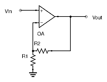
Since no current enters the Op-Amp, a simple voltage divider equation can give us  :
:  .
.
Applying , and since here  , we have:
![\[ V_{in} = \frac{R_1}{R_1+R_2}V_{out} \]](http://modernhamguy.com/wp-content/ql-cache/quicklatex.com-610e156e114305d6f0f8f5eb144c2932_l3.png "Rendered by QuickLaTeX.com")
Which gives us  . This circuit is an non-inverting amplifier with gain
  .
.
Conclusion
Hopefully this post gave you a good and easy-to-understand introduction to the Operational Amplifier. This was just a brief overview, but just with this you already have a solid base, and the most important characteristics have already been given. There are a few more specific things to learn, and we’ll get into the less obvious parts of Op-Amp application in the next few posts.