Introduction
When studying feedback, we are usually told that it “improves input and output resistances”, and often times we are just left with that. For us, future circuit designers, we need something much more precise. A more truthful version of the above sentence is that feedback CAN improve input and output resistances. But how and by how much does negative feedback impact these values? This post aims to clarify the problem and give you a quick and easy method to determine input and output resistances.
The Different Feedback Topologies
The first thing you need to know is if the feedback acts as to reduce or increase the input (or output) resistance. No calculations needed here, just a qualitative analysis. To answer this question, you need to recognize which feedback configuration is employed. As if feedback wasn’t already hard enough, you also have different ways to incorporate feedback.
The feedback topology depends on whether we amplify voltage or current, and on whether we are sampling voltage or current at the output for feedback use.
The Voltage-Voltage Configuration
Voltage is sampled at the output for feedback, and voltage is being subtracted at the input. Also known as series-shunt, as follows:
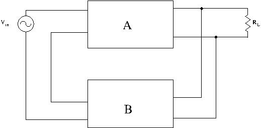
In this configuration, feedback increases input resistance and decreases output resistance.
The Current-Voltage Configuration
Current is sampled at the output, and voltage is being subtracted at the input. Also known as series-series:
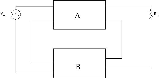
In this configuration, feedback increases both input and output resistance.
The Current-Current Configuration
Current is sampled at the output, and current is being subtracted at the input. Also known as shunt-series feedback:
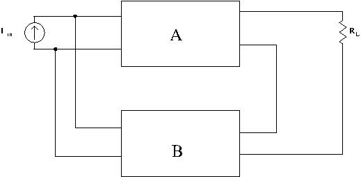
In this configuration, feedback decreases input resistance and increases output resistance.
The Voltage-Current Configuration
Voltage is sampled at the output, and current is being subtracted at the input. Also known as shunt-shunt feedback:
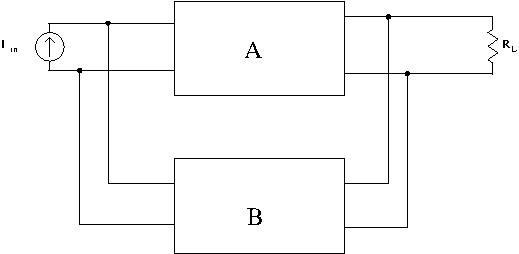
In this configuration, feedback decreases both input and output resistance.
What you Need to Remember
You don’t have to learn this by heart. Recognizing the correct topology might seem daunting, but actually putting this principle to use is not that complicated. All you have to do is ask yourself two questions:
- Before the feedback network, am I sampling a voltage or a current?
- At my input, is voltage or current being subtracted?
To better illustrate, let’s use a simple single transistor amplifier:
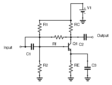
Here, output voltage is sampled, while current at the base is subtracted. Hence, input resistance and output resistance will be decreased.
Input Resistance of Feedback Amplifiers
To determine the real input resistance of our amplifier, we first need to find the input resistance with feedback switched off. This doesn’t mean removing  from the circuit, but removing the current flowing from the output back into the input. We are ignoring the portion of the current from the transistor’s dependent current source which is flowing through .
We can determine this initial input resistance the usual way, using a test voltage source and determining the ration  . Here,
  :
:


I’ve decided here to ignore the biasing resistors  and
and  , I’m assuming their values are high enough to be ignored. It also lightens the math a little, which is very useful for this example used for illustrative purposes.
Our total input test current is thus  .
.
Our input resistance, with feedback switched off, is then 
Now, if we want the input resistance with feedback, we could do the same calculation as above, using the superposition principle and taking into account the current flowing from the transistor dependent source into the feedback resistor. For the above example, this is a viable solution, since the circuit is relatively simple. However, a shortcut would be to exploit the loop gain of the circuit. Normally, when designing feedback amplifiers, you will calculate the loop gain, so at this point loop gain is a known quantity. We haven’t calculated it yet for this circuit, so let’s do it now:
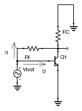
Following the steps outlined in the previous post, we (1) kill all sources, (2) cut the feedback loop at an arbitrary point, and (3) insert a resistance equal to the one the collector was seeing before the cut. The collector is chosen here. We then (4) apply a test signal after the cut. Here I decided on a test input current. We then travel the loop, and determine the ratio of output current over input current (5).
Again, ignoring biasing resistors, we have:  , giving us
  . Hence our loop gain is:
![\[ G_{loop} = \frac{ \beta R_C}{R_C + R_f + \beta r_e} \]](http://modernhamguy.com/wp-content/ql-cache/quicklatex.com-26eff555534f971dce81b8cace4d7a59_l3.png "Rendered by QuickLaTeX.com")
Now that we have our loop gain let’s get back to our input resistance. Remember when I told you that  is a magical quantity for feedback amplifiers? Just as gain was decreased by a ratio of
  compared to its open-loop variant, input resistance is either multiplied or divided by . Since in our example, current was subtracted from the input, then we are in a topology where feedback decreases input resistance. Hence, our true input resistance with feedback is:
![\[ R_{in} = \frac{R_{in}_0}{1 - G_{loop}} \]](http://modernhamguy.com/wp-content/ql-cache/quicklatex.com-45adc5bd7a33614f2f8b938bed3508f2_l3.png "Rendered by QuickLaTeX.com")
Remember that since feedback is negative,  is negative, so we need to add a negative sign to our above result for when using this equation.
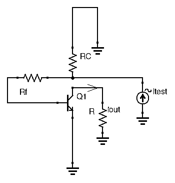
Output Resistance of Feedback Amplifiers
The same method is used to determine output resistance of feedback amplifiers.
Let us find the output resistance with feedback turned off, which means ignoring the current flowing from the transistor’s dependent current source back into the base through . Again, ignoring biasing resistors, we have:
![\[ i_{test} = i_1 + i_2 = \frac{v_{test}}{R_C} + \frac{v_{test}}{R_f + \beta r_e} \]](http://modernhamguy.com/wp-content/ql-cache/quicklatex.com-b51f1f094e15e79ee59bc8623df45296_l3.png "Rendered by QuickLaTeX.com")
Which gives us an initial output resistance of  .
.
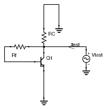
Here, output voltage is sampled at the collector, meaning here we are in a topology where feedback decreases output resistance. This means that the output resistance with feedback is the output resistance without feedback divided by the magical ratio :  .
.
Conclusion
While feedback amplifiers possess incredible qualities, the mathematics behind some essential characteristics such as gain and input/output resistances can become incredibly complex. Already with just a single transistor, and ignoring a few components, we still have results that are far from trivial. Some textbooks will give you a huge general expression with countless factors. Don’t be intimidated by these. Just remember, once you have your loop gain, just calculate your input or output resistance as you usually would, divide or multiply by  , and you’re good to go.