Introduction
We’ve seen that a Common Base amplifier has a bigger bandwidth than the Common Emitter amplifier as it doesn’t suffer from the Miller Effect. However, the low input resistance of the CB amplifier can be a problem: it can draw lots of current from the preceding stage, greatly “loading” it and altering its intended behavior. It’d be great if there was a way to keep the high input resistance of the CE amplifier while also having the higher bandwidth of the CB amplifier.
It turns out there is a solution. By combining both the CB and CE amplifier configurations, we can get the best of both worlds.
The Cascode Amplifier Circuit
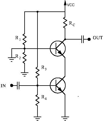
The above circuit is called a Cascode Amplifier. It combines two classical configurations: the Common Base and Common Emitter configurations.
The bottom transistor is in a Common Emitter configuration.  and
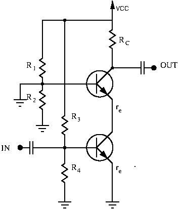
and  form a voltage divider and give a bias voltage to the transistor. However, unlike our classical common emitter amplifier, there is no collector resistance. So how can we calculate the voltage gain of this stage? Note that the collector leg of the bottom transistor connects to the emitter leg of the top transistor. Even without any external resistor added to the circuit, the emitter of a transistor exhibits resistance:
  . There is roughly the same current flowing through both transistors, so
  for both transistors is equal.
We can now determine the voltage gain of the bottom stage:  . The common emitter stage of the cascode amplifier has no voltage gain. Looking back at the miller formula:
  . The apparent BC capacitance is now only
  . Without any voltage gain, the Miller effect is cancelled, thus greatly increasing the bandwidth of the circuit. While this stage doesn’t have voltage gain, it still has a current gain of
  , and a high input resistance.
The top transistor is in a Common Base configuration.  and
and  form a voltage divider and bias the transistor. We can easily find the voltage gain of this circuit:
  . As we saw previously when studying the different configurations, the Common Base configuration has voltage gain, but no current gain. This stage also has relatively high output resistance.
Conclusion
The common emitter stage provides current gain and high input resistance, while the common base stage provides voltage gain and high output resistance.
In the past, this configuration was widely used in VHF and above to increase bandwidth. Nowadays however, we have RF transistors available on the cheap with reduced parasitic capacitance. This circuit is still good to understand however, as you’ll probably need its advantages one day when designing your own circuits, or even just to be able to understand ham circuits.
To recap, the cascode amplifier has:
- high input resistance
- moderately high output resistance
- good power gain
- great bandwidth