Introduction
Now that you have the basics needed to understand and analyze transistor circuits, let’s continue our study with the classical textbook configurations of BJT amplifiers. You’ll find these in every course and textbook that deals with amplifiers, though not always with great explanations.
The following circuits are textbook circuits, and while you may find them used as is in ham circuits, chances are the BJT amplifiers you will find in the ham literature won’t look like these examples at all. Don’t despair if you don’t understand them after reading this chapter. We will see how to improve on these amplifier circuits and how to optimize their behavior later on, after which most amplifier circuits should make much more sense to you.
The Three Configurations
A BJT has three ports: base, collector, and emitter. There are then 3 configurations possible that depend on which port is ‘common’: common-emitter, common-collector, and common-base.
What does ‘common’ mean? For our purposes, ‘common’ here means ‘AC-grounded’. If you’re a bit rusty on your electronic fundamentals, check out this page before moving on.
Here are the three classical configurations for BJT amplifiers:
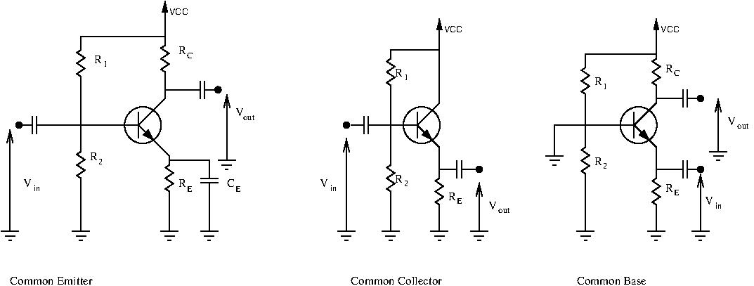
Let’s explain why they are named this way. Take a look at the common-emitter amplifier. A first glance, none of the ports are grounded. Recall however that a capacitor is a short circuit for AC signals. Thus, here, the emitter is AC-grounded, and is then ‘common’. The input signal is applied at the base, and the output signal is sampled at the collector.
Next, let’s look at the common-collector amplifier. Same as before, at first glance none of the ports seem grounded. However, we know that a constant voltage source is seen as ground for AC signals. Thus, here, the collector is AC-grounded. The collector port is ‘common’. The input signal is applied at the base, while the output signal is sampled at the emitter.
Finally let’s look at the common-base amplifier. We can see plainly that the base port is grounded. It is ‘common’. The input is applied at the emitter, and the output is sampled at the collector.
Each of these configurations have widely different characteristics and are used for different purposes. In the following chapters, we will derive the following characteristics for each of these amplifiers:
- Voltage gain
- Current gain
- Input resistance
- Output resistance
- Biasing
Conclusion
This was just a small overview of what we will be covering very soon. These next chapters are very important and form the basis for understanding more complicated amplifiers and circuitry. Amplifiers are widespread in all areas of electronic engineering, and knowing how to analyze and design them will give you a big leg up in the world of electronics. Many people stick to learning just one of these configurations (most often the common-emitter) and don’t use the others. Keep in mind that all three have their uses, especially in RF work. Learning them may take you some time, but it will pay big dividends later down the line.