Introduction
The common drain amplifier is analogous to the common collector amplifier, and it is also called the source follower amplifier, as will become clear very soon. As usual, we will derive the voltage gain, current gain, input resistance, and output resistance of this amplifier.
The Common Drain Amplifier

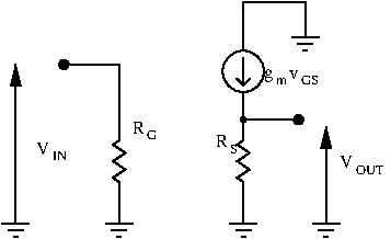
This is the common drain amplifier. The input is applied at the gate, while the output is sampled at the source. AC signals sees constant voltage sources as ground, so the drain is AC-grounded. The drain is “common”.
Voltage Gain
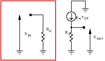
Let’s draw the small signal equivalent circuit of the common drain amplifier, without the load:
To find the voltage gain, we need to calculate  :
:


Thus, we have:
![\[ v_{OUT} = R_S g_m (v_{IN} - v_{OUT}) \]](http://modernhamguy.com/wp-content/ql-cache/quicklatex.com-6750bf577862088d0d3a21e4ddff050b_l3.png "Rendered by QuickLaTeX.com")
![\[ v_{OUT} = R_S g_m v_{IN} - R_S g_m v_{OUT} \]](http://modernhamguy.com/wp-content/ql-cache/quicklatex.com-d331977ea275ed4fbadd7a2bb549e541_l3.png "Rendered by QuickLaTeX.com")
Rearranging terms, we obtain:
![\[ v_{OUT}(1 + R_S g_m) = R_S g_m v_{IN} \]](http://modernhamguy.com/wp-content/ql-cache/quicklatex.com-74dc84a0d930a20eb1dc874805ec5ecf_l3.png "Rendered by QuickLaTeX.com")
![\[ A_v = \frac{R_s g_m}{1 + R_S g_m} \approx 1 \]](http://modernhamguy.com/wp-content/ql-cache/quicklatex.com-9743a2bb2aec6ebe12edae375241d0f5_l3.png "Rendered by QuickLaTeX.com")
Just like our common collector amplifier, the common drain amplifier has unity voltage gain. The output voltage follows the input voltage: for this reason the common drain source amplifier is also called the source follower.
Current Gain
Input is applied at the gate, but a JFET’s gate draws no current. This circuit draws no current from the input (apart from the negligible amount passing through  ), but supplies current at the output. Current gain is infinite.
Input Resistance
Input resistance is  and is very high.
Output Resistance
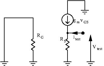
To find the output resistance, we ground the input signal, and apply a test signal at the output. Then, we calculate  :
:
![\[ i_{test} = \frac{v_{out}}{R_S} - g_m V_{GS} = \frac{v_{out}}{R_S} - g_m (v_G - v_S) \]](http://modernhamguy.com/wp-content/ql-cache/quicklatex.com-fbe2a8887570420d98ba239ff4d619db_l3.png "Rendered by QuickLaTeX.com")
The input is grounded so  , and our test signal is applied at the source terminal, so
  :
:
![\[ i_{test} = \frac{v_{out}}{R_S} + g_m v_{test} \]](http://modernhamguy.com/wp-content/ql-cache/quicklatex.com-7ae124c625afa5391dc5ad8f37689c00_l3.png "Rendered by QuickLaTeX.com")
![\[ i_{test} = v_{test} (\frac{1}{R_S} + g_m) \]](http://modernhamguy.com/wp-content/ql-cache/quicklatex.com-542ce6d8daaa521ea9961615a981a91d_l3.png "Rendered by QuickLaTeX.com")
We can now calculate our output resistance  :
:
![\[ R_{out} = \frac{v_{out}}{i_{test}} = \frac{v_{test}}{v_{test} (\frac{1}{R_S} + g_m)} = \frac{1}{\frac{1}{R_S} + g_m} \]](http://modernhamguy.com/wp-content/ql-cache/quicklatex.com-9a697b0ce49704ad35a05b90e0d71868_l3.png "Rendered by QuickLaTeX.com")
![\[ R_{out} = \frac{R_S}{1 + g_m R_S} \]](http://modernhamguy.com/wp-content/ql-cache/quicklatex.com-23e0f0b8a9db4f339ae5687e1db5fdf6_l3.png "Rendered by QuickLaTeX.com")
![\[ R_{out} \approx \frac{R_S}{g_m R_S} = \frac{1}{g_m} \]](http://modernhamguy.com/wp-content/ql-cache/quicklatex.com-0c967f30e7cce9daa8e3c2f159ebd771_l3.png "Rendered by QuickLaTeX.com")
The output resistance is  , which is low.
Conclusion
Just like the common collector amplifier, the common source amplifier has:
- high input resistance :
- low output resistance:

- unity voltage gain
- current gain
And just like the common collector amplifier, this circuit makes an excellent buffer. Its high input resistance prevents loading preceding stage, and its low output resistance allows to easily supply a certain voltage to the next stage.