Introduction
Oscillators. There is probably no other type of circuit that has received quite as much popularity from hams as oscillator circuits. If you look at the ham literature, you will see a ton of designs for oscillators. A great number of these designs are dedicated to the HF bands. Because of the huge database of designs available, new (and older!) hams and experimenters can sometimes feel overwhelmed. Furthermore, what makes an oscillator work, and what makes one design better than the other, is often not well understood, and many relegate oscillator design to some form of mystic art.
While it is true that at first glance oscillator circuits can seem complicated, in truth, despite the hundreds of different oscillator designs available, they are all derived from just a few possible architectures. Knowing the fundamental theory and architecture behind oscillator circuits will allow you to make sense of most oscillator designs, and also allow you to design your own.
In this post, we’re going to specifically address the LC oscillator circuit, arguably the most popular and well known oscillator in the ham radio world.
The Problem With RF Oscillators
When designing an oscillator, there are many families of oscillator circuits to choose from, some much simpler than others. Unfortunately, once we get in the MHz range, those options shrink. Many of the easiest and smallest kinds of oscillators don’t work or just aren’t stable, clean, or accurate enough to use for RF applications. Contrary to most digital applications, RF oscillators need to have a certain spectral purity (least amount of harmonics as possible) and stability. This limits our choice of oscillator family.
For HF and VHF bands, one popular solution is the LC oscillator. While not found in commercial gear anymore (digital frequency synthesis can now fit a highly tunable, stable, wide-range oscillator circuit in a very small space format), it is still a very common circuit for hams to build. Its all analog design means no need to delve into micro-controllers. LC oscillators, if well designed, can be very stable and output a very clean signal.
There are two major drawbacks to the LC oscillator however. One, its tuning range is relatively limited. And two, the main components needed to build a good LC oscillator are nearly extinct. As we’ll see in the next few sections, LC oscillators are tuned with variable capacitors and/or variable inductors. The only way to get those today would be to pay through the nose for decades-old surplus, pay even more for the very few specialty enthusiast manufacturers of these components out there, or to build them yourself (requiring special tools and know-how). You will find “variable” capacitors in nearly all the major electronic retailers, but these are actually trimmer capacitors, and are not meant for user interaction. They are much more fragile, and are instead meant to be adjusted a few times in the lifetime of a circuit.
IF you do decide on an LC oscillator for your design, and don’t want to use trimmer capacitors, I suggest building your own variable inductor. Much simpler than building a variable capacitor, and if well designed it can also take up relatively little space.
LC Resonant Circuits
Before studying LC oscillator circuits right away, we need to understand LC resonant circuits. These circuits form the basis of every LC oscillator design out there. Thankfully, the theory is relatively simple, and if you’ve done some electronics in high school, this will sound familiar.
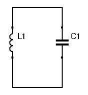
The above diagram features an LC circuit. If we apply a momentary voltage spike at the capacitor, we charge that capacitor:its electrical field is being charged. The capacitor will then discharge itself into the inductor, releasing the energy stored in its electrical field. Even when the capacitor is completely discharged, current still flows through the inductor. Indeed, while it was being charged by the capacitor, energy was being built up in the inductor’s magnetic field. Once the capacitori is completely discharged, the magnetic field forces current through until that field collapses (a simpler way to see it is that an inductor works to fight current variations). That current goes to charge the capacitor, and the cycle begins anew. Thus, an LC circuit when excited creates oscillations. These oscillations are sinusoidal, and their frequency is equal to  . Unfortunately, these oscillations don’t last forever. No circuit is perfect, and inside this LC circuit are internal resistances. Eventually the oscillations will be dampened and die out.
LC circuits store energy, and are frequently called tank circuits.
Basic Oscillator Theory
To prevent those oscillations from dying out, we need a way to sustain them. By using that same circuit, but adding in an amplifier to avoid the dampening of the oscillations, we create an oscillator. To create an oscillator, a certain amount of oscillation is fed back to the LC tank circuit, therefore sustaining the oscillations.
The amplification needs to be carefully selected as to be big enough to allow sustained oscillations, but also small enough to avoid saturation. In theory any active device can be used, but in practice BJTs and JFETs are the most commonly used. Op-amps rarely have the necessary bandwidth to be useful in RF oscillators.
Depending on how the amplifier and the LC circuit are arranged, multiple topologies can be created. The two most common topologies are the Colpitts and Hartley oscillators.
Colpitts Oscillators
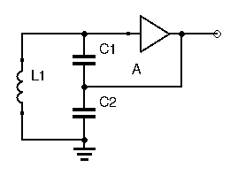
In a Colpitts oscillator, the feedback is applied between 2 capacitors in the LC circuit. How are the oscillation sustained in this configuration? The two capacitors act like a voltage divider circuit. Applying a signal between  and
and  will cause a greater signal to appear at the active device’s input. For this to work the amplifier needs to have gain less than 1, or else the circuit will fall into saturation. For this reason, many practical Colpitts (and Hatley) oscillator designs use the Source-Follower or Emitter-Follower amplifier configuration, which has a slightly less-than-unity gain.
The resonant frequency is calculated the same way as a usual LC tank circuit. Keep in mind the rule for simplifying capacitances:
- if in series:
 , just like parallel resistances
 - if in parallel:
 , just like series resistances
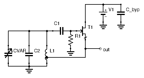
While you will often find Colpitts oscillators with many more components and a seemingly more complicated architecture, a simple design without any frills can still perform admirably well, such as the circuit below:
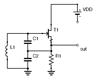
This circuit uses a Source-Follower configuration, the output being sampled at the source. The power supply bypass capacitor is not represented.
So far, none of the oscillators we’ve presented were tunable: they all were set at a single frequency. If we want to vary the frequency, we need to change one of the parameters in the  equation. Most designs will choose to incorporate a variable capacitor in the LC tank circuit. That said, nothing is stopping you from adding in a variable inductance instead. It’s just easier to get a hold of variable capacitors.
Where can we add that variable capacitor? For the oscillator to work well, it’s recommended to keep and equal in value, so making them variable is out. Instead, the variable capacitor can be added in parallel, as shown below:
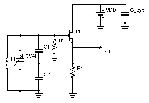
The larger and values of the capacitive divider, along with the inductance  , account for the bulk of the frequency determination. The smaller
  is used for tuning. is generally in the tens of picofarads, while and are generally in the hundreds of picofarads or more. This configuration is called the Parallel-Tuned Colpitts, since the variable component,
  , is in parallel to the rest of the LC circuit.
  is a high value resistance (in the hundred of kOhms range), making sure the gate always has a path to ground and is never left floating.
Another Colpitts configuration is possible: the Series-Tuned Colpitts, in which the variable capacitor is in series with the inductance, as follows:
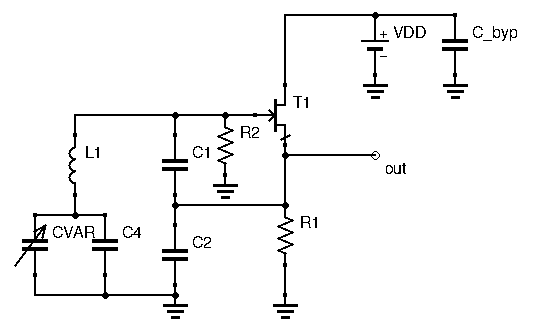
This circuit is also called the Clapp Oscillator. In this configuration, you will sometimes find an extra capacitor  across the variable capacitor. Adding a fixed capacitance across a variable capacitance will decrease the tuning range. Indeed, let’s take an example with able to vary between 10pF and 25pF, and let’s add a parallel capacitance of 50pF. Then:
- at 10pF, equivalent capacitance becomes

- at 25pF, equivalent capacitance becomes

We have effectively changed the capacitance tuning range from  to
to  . This lower range of capacitance also means less frequency sweeping. This is useful if you have a larger than needed variable capacitor, or to neatly adjust the tuning range to your required band. Indeed, you’ll rarely find the exact variable capacitor or trimmer required for your design. Being able to tweak that effective variable capacitance with the help of a small parallel capacitance is useful in this case, allowing you to restrain your oscillator to its required frequencies.
So far we’ve only used JFETs in our examples. It is traditionally the recommended active device to use when designing oscillators. JFET’s are less noisy components, and their greater input resistance and lower output resistance make oscillator designs less finicky. That said, it is absolutely possible to create good-performance oscillators using BJTs:

Hartley Oscillator
The other LC oscillator configuration is the Hartley oscillator. In this configuration, instead of using two capacitors to boost up the voltage at the active device’s input, here a tapped inductor is used instead. The output signal is applied at the tap, typically around 20% of the length of the inductor, while the input (gate or base) sees the entirety of the inductor voltage. The inductor here acts as a transformer, taking a sample voltage at its tap and increasing it before presenting it to the input, therefore compensating the less-than-unity amplifier gain.
Other than that, it works the same way a Colpitts oscillator does. Extra capacitances can be added in parallel to change the resonant frequency, and a variable capacitor allows tuning. There is one difference however. Notice the coupling capacitor . This capacitor limits the amount of power transferred from the LC circuit to the gate, therefore decreasing the tank circuit’s loading and helping to stabilize operating frequency. Its value is small, in the picofarad range, thus giving it a higher impedance. When designing Hartley oscillators, you’ll need to try out different values for and check for oscillator action. A common value to start with is 2.7pF. Choose the lowest value that allows proper oscillation.
Other LC Oscillators
Sometimes you’ll come across LC oscillators with names other than Colpitts or Hartley. While all LC oscillators are variants of either the Colpitts or Hartley oscillator, some variants will sometimes have different names. As explained above for example, the series-tuned Colpitts is also called the Clapp oscillator. Another variation of the Colpitts oscillator is the Seiler oscillator. Seiler oscillators include an extra capacitor in parallel with the inductance.
A less well-known variant is the Vackar oscillator, featuring greater tuning range. Its complexity is greater than the other variants, and little documentation on it is available. A few high-performance VFO circuits based on the Vackar oscillator are nonetheless available on the internet if you’re interested.
Designing LC Oscillators
With the great number of LC oscillator designs by hams floating around it might seem like there are myriad ways to design one and get creative. As great as that would be, this is an illusion. While there are indeed hundreds of LC oscillator circuits freely available, all of them are variants of the Colpitts or Hartley oscillator. Designing an LC oscillator can go two ways. Either you start with a classic Colpitts or Hartley oscillator as shown in the above paragraphs, and adjust component values for your desired frequency. From there extra capacitors can be added to shift the frequency, and bias components can be altered. Or, you can pick up an existing design you find promising, and tweak it to your needs. In fact, the ARRL Handbook does a great job of explaining LC oscillator design: “…very few professional or amateur designers have ever designed an oscillator from scratch. We all have collections of circuits we’ve “harvested”, and we adjust a few values or change a device type to produce something to suit a new project.”
Conclusion
When attempting to design an oscillator, the very first type that hams gravitate to is usually the LC oscillator. There are hundreds of designs already freely available, and if built with good components, specifically NP0 capacitors, the oscillator can be made stable and relatively pure. A well-built LC oscillator not only performs well, it looks sublime as well. There is just something about old-school variable capacitors that makes the experience so satisfying.
That said, LC oscillators would not be my first choice. They suffer from extremely limited tuning (although that can be alleviated somewhat by changing tank circuits for each band, but this requires more complex circuitry), they are very expensive to build (silver mica capacitors, offering great thermal stability, are usually employed, and they are costly. Lets not forget the cost of the variable capacitor as well…), and they often require some tweaking to actually work (though to be fair, that is part of the fun). There is a reason commercial gear hasn’t used LC oscillators for decades. If you love designing these, or are into restoring old radios, then by all means build away! If you’re a beginner looking to get into the more technical side of ham radio, I can’t recommend using this kind of oscillator. Instead, I would highly suggest using some kind of frequency synthesis, a subject we will get into soon. With today’s technology, frequency synthesis not only allows a huge tuning range, it now also offers a clean signal and a super-stable output.