Our first post on mixers focused on essential mixer theory and passive mixers. Understanding the diode double-balanced mixer is a great start, but that still leaves many mixer architectures unexplored. Some of the most popular mixers used in to today’s commercial and amateur gear are active mixers, and it makes sense to dissect the more well known ones.
Why Use Active Mixers
The most commonly used passive mixer is the diode double-balanced mixer. Its good dynamic range, moderate noise figure, high intercept, and all-around good performance make it a popular choice. However, it’s impossible to get around its conversion loss. This is where active mixers come in. They can not only provide gain, but also need less LO drive power to work. Most commercial, amateur, and many ham-built circuits include active instead of passive mixers.
Understand Active Mixers
Covering every active mixer architecture would not be very useful, there are only two ways active devices can be used to create a mixer: either by relying on the same switching action as the diode double-balanced mixer explained in the previous post, or by exploiting an active device’s non-linearity to approximate multiplication.
In this article we will cover two different and popular active mixers: the simple JFET mixer, and the Gilbert-Cell mixer.
The JFET Mixer

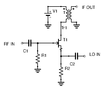
While probably the simplest circuit to build, how it is able to multiply signals isn’t intuitive at all. This is one of the few active mixers that doesn’t really rely on switching, but instead exploits a JFET’s non-linear characteristic. Analyzing the circuit will reveal how exactly this circuit can multiply signals.
First, let’s recall a JFET’s characterstic equation, linking Gate-Source voltage to output drain current:
(1) ![]()
With:
 being the output drain current
 being the JFET saturation current
 being the JFET’s cut-off voltage.
In this circuit, the RF signal is applied at the Gate, while the LO signal is applied at the Source. Let the RF signal be ![]() and the LO signal be
and the LO signal be ![]() . The Gate-Source voltage then becomes:
. The Gate-Source voltage then becomes:
![]()
Replacing ![]() in equation (1) with the above expression, we obtain:
in equation (1) with the above expression, we obtain:
![]()
Developing the squared expression, we have:
![]()
Again, developing the squared expression gives us this very long equation:
(2) ![Rendered by QuickLaTeX.com \begin{align*} I_D = I_{DSS} [1 - \frac{2A\sin(2\pi f_1 t)}{V_{GS}_{off}} + \frac{2B\sin(2\pi f_2 t)}{V_{GS}_{off}} + \frac{A^2\sin^2 (2\pi f_1 t)}{V_{GS}_{off}^2} + \\ \frac{B^2\sin^2 (2\pi f_2 t)}{V_{GS}_{off}^2} - \frac{2(A\sin(2\pi f_1 t) B\sin(2\pi f_2 t)}{V_{GS}_{off}} ] \end{align*}](http://modernhamguy.com/wp-content/ql-cache/quicklatex.com-b60d81e8acca45b2320ff25f44f79fbc_l3.png)
I think you can see where this is going. Notice the last term in the above expression: it contains ![]() ! This equation is getting messy, so let’s simplify all the constants and see which frequencies we end up with:
! This equation is getting messy, so let’s simplify all the constants and see which frequencies we end up with:
(3) ![]()
Applying the following trigonometric identities:
Gives us:
(4) ![]()
Our output drain current thus consists of the following frequencies:
Our wanted frequency is either ![]() or
or ![]() . Regardless of which is wanted, the other unwanted frequencies are far away, and thus can be easily filtered out.
. Regardless of which is wanted, the other unwanted frequencies are far away, and thus can be easily filtered out.
This JFET circuit and its underlying math forms the basis of JFET mixers. Many practical JFET mixers are simply variations on this one.
The Gilbert Cell Mixer – A Simplified Approach
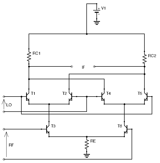
The Gilbert Cell mixer appears very often in both commercial and ham gear. The very popular NE602 (now known as the SA602/SA612) used in many ham circuits is actually a Gilbert Cell mixer in IC packaging. Below is the schematic of a Gilbert Cell Mixer, without any of the bias circuitry to keep it readable:

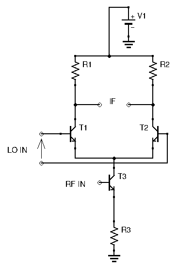
Intimidating, isn’t it? Honestly, trying to understand this circuit without any direction is an exercise in frustration for the beginner. Unless you’ve been experimenting for a while of have seen this circuit before, you will probably have trouble analyzing it. There is a simple way to make sense of it however. First, instead of studying the whole thing, let’s break it down first, and look at one half of the Gilbert Cell Mixer:

This looks more manageable. How does this circuit work? RF is applied at the bottom transistor’s base. This transistor is in a common emitter configuration, hence the input RF is amplified, and the output is found at the collector. Hence, both upper transistors have the same amplified RF signal at their emitter. Don’t forget that these transistors are biased (not shown on the diagram for reading ease), the amplified RF signal is a purely positive signal: it’s an AC signal with DC offset, the DC offset being equal to the collector bias voltage.
Now let’s take a closer look at the upper transistor pair. They are identical and biased the same way. However, the LO signal is applied differentially between both bases. At every LO clock pulse, one transistor shuts off and one transistor conducts fully. The transistor states changes at every LO clock pulse. The two transistors act like switches and their purpose is to alternate the RF signal between the two collectors. Sampling the result at the IF output gives us RF, phase shifted by 180° (inverted) at every clock pulse. In other words, the same switching action that is achieved by a the diode double-balanced mixer is here done by this transistor pair. While this explanation is relatively simple, it assumes the Gilbert Cell mixer is only useful with a square wave LO, as a switching mixer. This is not true, and the Gilbert Cell mixer actually multiplies analog signals via clever use of differential amplifier pairs.
The Math Behind Gilbert Cell Mixers
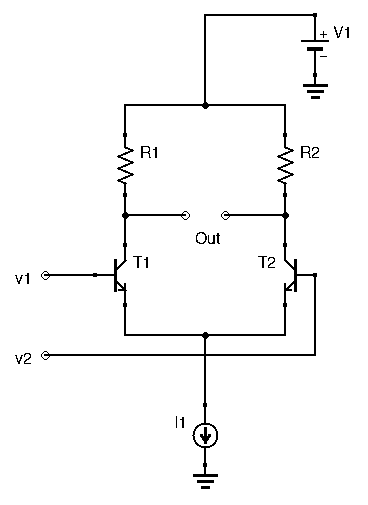
In case you haven’t read my article on differential transistor amplifiers, I’ll give a short review here:

Here, ![]() . Both transistors are in a common-emitter configuration so gain for each leg would be
. Both transistors are in a common-emitter configuration so gain for each leg would be ![]() , with
, with ![]() , with
, with ![]() in mA. In most applications of the differential amplifier, an emitter resistor is used to swamp
in mA. In most applications of the differential amplifier, an emitter resistor is used to swamp ![]() to more closely control gain, avoid temperature dependence, and avoid current dependence. For the Gilbert Cell mixer however, we WANT the gain to vary with current, and we’ll see why later. The differential amplifier’s gain here is
to more closely control gain, avoid temperature dependence, and avoid current dependence. For the Gilbert Cell mixer however, we WANT the gain to vary with current, and we’ll see why later. The differential amplifier’s gain here is ![]() . Both transistors being identical, they have the same bias current flowing through them. This means that each leg sees half the current
. Both transistors being identical, they have the same bias current flowing through them. This means that each leg sees half the current ![]() . Thus, our differential amplifier’s gain becomes:
. Thus, our differential amplifier’s gain becomes:
![]()
The essential thing to understand here is that gain is a function of ![]() . All that is required for this circuit to become a multiplier is to make
. All that is required for this circuit to become a multiplier is to make ![]() proportional to some signal we want to multiply with
proportional to some signal we want to multiply with ![]() :
:

![]() in this circuit controls current
in this circuit controls current ![]() , and subsequently determines emitter current for both
, and subsequently determines emitter current for both ![]() and
and ![]() . Since
. Since ![]() controls
controls ![]() ‘s gate, and since
‘s gate, and since ![]() ,
, ![]() ‘s collector current
‘s collector current ![]() becomes
becomes ![]() . Hence,
. Hence, ![]() is now proportional to
is now proportional to ![]() ‘s input, the RF signal.
‘s input, the RF signal.
Grouping all constants into ![]() , the upper differential pair’s voltage gain now becomes:
, the upper differential pair’s voltage gain now becomes:
![]()
This circuit is a multiplier.
The complete Gilbert cell is simply two of these circuits paralleled.

The lower differential pair ![]() and
and ![]() have their gain set by their common emitter resistance
have their gain set by their common emitter resistance ![]() . The RF signal is differentially applied to
. The RF signal is differentially applied to ![]() and
and ![]() , sending the RF signal to
, sending the RF signal to ![]() and
and ![]() ‘s emitter, and a 180° phase shifted version of it to
‘s emitter, and a 180° phase shifted version of it to ![]() and
and ![]() . Thanks to the action described above, the RF signal is multiplied by the LO signal, and the resulting waveform is found by sampling the voltage drop across the IF ports. Paralleling the basic differential transistor multiplier improves port-to-port isolation.
. Thanks to the action described above, the RF signal is multiplied by the LO signal, and the resulting waveform is found by sampling the voltage drop across the IF ports. Paralleling the basic differential transistor multiplier improves port-to-port isolation.
Using Gilbert Cell Mixers
These mixers work best when the transistors are matched. While Gilbert Cell mixers can absolutely be built using discrete components, it is much more common to see them in packaged IC form. IC Gilbert Cell mixers can guarantee transistor matching, and are ready to use out of the box, with all of the biasing already taken care of. Their ease of use and good performance have made them very popular among hams and RF engineers. They also typically cost less than diode double-balanced mixers in IC form and are much easier to find.
While they often are the first pick for beginner homebrewers when choosing a mixer for their designs, keep in mind that they have a lower intercept than diode DBMs. While the Gilbert Cell mixer can be used as a front end mixer with adequate results, if high performance is required it is better to opt for a mixer with a higher intercept.
Conclusion
In this post we’ve covered two types of active mixers. The basic JFET circuit is useful to understand as many JFET mixers are based on it. And of course it makes sense to understand the Gilbert Cell mixer as it is very commonly used, not only in ham equipment and homebrew circuits, but also in commercial gear. There are still a couple more mixer topologies I want to explore, but having a good understanding of diode DBMs and Gilbert Cell mixers already provides you with a great knowledge base in mixer theory.